
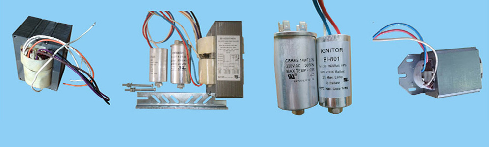
Electronic ballasts resonant inverter circuit, comprising the EMI filter, the diode bridge, APFC control circuit, the inverter circuit, the parallel resonance circuit, the lamp load circuit, a phase compensation circuit, wherein: APFC power factor control circuit forcorrection, so that the input power factor of 0.98 or more, the input current harmonics up to standard; inverter circuit to provide energy for the parallel resonant circuit; parallel resonant circuit for generating a high voltage higher than the breakdown voltage of the fluorescent tube; lamp load circuit waslimiting negative resistance characteristics of the fluorescent tube; the phase compensation circuit, and the lamp load circuit at the same time in parallel to the output of the parallel resonant circuit, with the lamp load circuit of the current phase difference of 180 °, between the two vectors and flowing through the parallel resonant circuitcurrent. The electronic ballast with a constant high frequency output (error <0.8%), and a rated power output of the lamp current to the stable sinusoidal constant current source (THD <1%), with a ± 15% adjustment range, high reliability characteristics. The test load is currently widely used in various types of fluorescent ballasts.
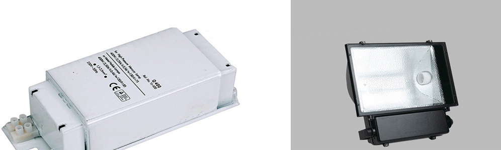
Metal Halide Ballasts | High Pressure Sodium Ballasts | Fluorescent ballasts | Gear Tray
Links: Porcelain lamp socket | Mercury Vapor Ballast | Light bulb socket
Xml Copyright: @2012-2020 James Lighting Electronic Co.,Ltd


 EMAIL US
 SKYPE
SKYPE