
Electronic ballast is the power frequency (50Hz / 60Hz) alternating current into high frequency alternating current, and can make a or a plurality of fluorescent tube normal startup and steady work of converter (ballast) basic principles:
AC / DC converter, which is composed of a full bridge rectifier, and other complete, rectifier by electromagnetic interference (EMI) filter (RFI), consisting of an inductor L and a capacitor C, prevent ballast to produce harmonic feedback to input grid, suppression of pollution of power grid and the equipment interference. At the same time, stop the power grid harmonic interference into the ballast. Before the DC filter, the power factor correction (PFC) boost circuit can reduce the current harmonic distortion and improve the power factor. Composed of bipolar or MOS - FET, power transistor DC / AC inverter DC voltage converter for 20 ~ 50KHz high-frequency sine wave voltage, output network uses the LC series resonant self-excited circuit or excitation circuit.
High frequency resonance causes the starting capacitor to generate high voltage pulse to light the lamp,
After the start of the inductor current limiting function, auxiliary circuit to improve the safety, reliability, solve the lamp circuit matching, including preheating and starting circuit, an abnormal state protection circuit, high frequency feedback and control circuit
There are many kinds of inverter topologies used in ballast. According to the input voltage, load power and cost considerations can choose flyback flyback), push pull (push pull) and half bridge (half bridge) such as topological structure.
The common half bridge topology. The resonant circuit includes series resonant, parallel resonance and series parallel resonant circuit,
Series parallel resonant circuit is commonly used in the rectifier circuit. Half bridge inverter circuit topology and series parallel resonant circuit can be composed of D common ballast circuit
Class series parallel resonant converter, the pre - stage rectifier module and the power factor correction (PFC) module provide the DC voltage, typically 400V. After the switch tube S2, S1 close to 50% duty cycle of rotation, for LCR
The resonant circuit provides an input voltage close to the square wave. Resonant inductor and resonant capacitor, they are the main parameters we need to get in the design. In the preheating stage,
The equivalent resistance of the fluorescent lamp tube is very large, and only a very small electric resistance of the filament and the resonant inductance and resonant capacitor series resonance,
The resonant circuit can form a high ignition voltage at both ends of the tube. After the fluorescent lamp is ignited, the electric arc equivalent resistance Rlamp of the lamp tube is in a few hundred ohm,
The filament resistance can be neglected. Rlamp resonant inductor and resonant capacitor series parallel resonance, at the end of the tube is applied to 40KHz about the high frequency sinusoidal voltage, in
Lamp voltage lower than the output voltage of the electronic ballast, in order to normal light fluorescent lamp must rely on current limiting inductance and capacitance starting between series resonance, to improve and meet the working voltage of the lamp tube; and series resonance of establishment, we must ensure that in specific work frequency invariant, current limiting inductance inductance and capacitance starting capacitance equal; In electronic ballast, the current limiting inductance and the value of the starting capacitor can not be changed once it is determined.The accuracy and stability of the electronic ballast operating frequency are guaranteed,The key problem of the electronic ballast work quality.
Fluorescent light fixture belongs to the cathode preheating start type electric light source, high pressure cold start, easy to produce filament sputtering damage phenomenon filament, appear cathode tube wall early blacking, shorten the lamp life, start preheating, reduced voltage starting (300 ~ 400V. The advantages of PTC thermistor: small size, simple circuit, low cost, its disadvantages: line power loss increases (consumable about 0.8W), luminous flux and luminous coefficient decreases, produces the high temperature caused by thermal radiation. Power large PTC should choose low resistance and large size, long preheating time PTC should choose high Curie point, large size abnormal state refers to the lamp open circuit, short circuit, overload, don't start etc. five lamp phenomenon is open across the resonant capacitor has continued more than 700V high pressure and large resonant current, easily damaged power tube.
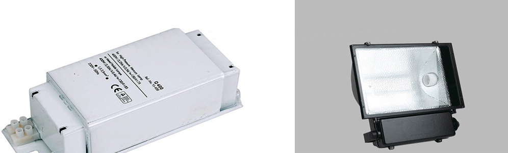
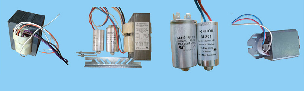
Metal Halide Ballasts | High Pressure Sodium Ballasts | Fluorescent ballasts | Gear Tray
Links: Porcelain lamp socket | Mercury Vapor Ballast | Light bulb socket
Xml Copyright: @2012-2020 James Lighting Electronic Co.,Ltd


 EMAIL US
 SKYPE
SKYPE