
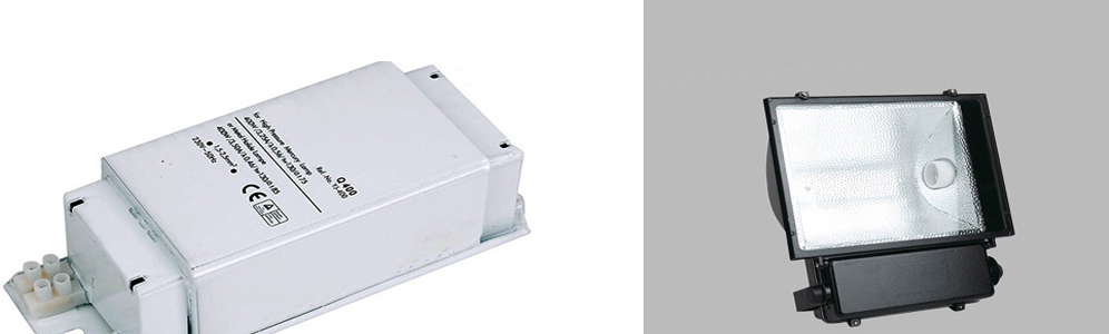
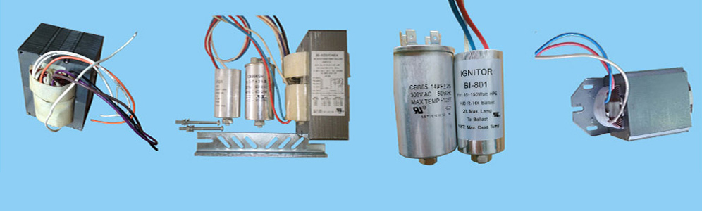
The most HPS ballasts is nothing more than a current limiting device, such as an inductor, resistor or capacitor. For 50 and 60 Hz applications, the most common current limiting device is an inductor. A simple current limiter works best when the line voltage is at least 2 times the lamp voltage. So, a simple inductor can be used in Europe, where the line voltage is 220 to 240 VAC, to operate a 4 foot lamp, which operates at 85 to 100 volts, depending upon design. In the US and other places that use 120 VAC lines the ballast is a combination autotransformer (to raise the voltage) and inductor (the current limiter).In addition, a Rapid Start ballast has additional windings to supply about 3.6 VAC to heat the filaments.
The wiring diagram is the blueprint for the ballast circuitry, including the input supply voltage and grounding methods. A ground connection must be made to all ballasts to avoid shock hazard, personal injury or damage to the luminaire or installation. Ballast installations and groundings should be made in accordance with all applicable government codes and regulations where required.
Metal Halide Ballasts | High Pressure Sodium Ballasts | Fluorescent ballasts | Gear Tray
Links: Porcelain lamp socket | Mercury Vapor Ballast | Light bulb socket
Xml Copyright: @2012-2020 James Lighting Electronic Co.,Ltd


 EMAIL US
 SKYPE
SKYPE