
Fluorescent lamp 20W and 40W aging, the electrician replaced all magnetic ballast to electronic ballasts. But a small part of the electronic ballast arise after installing a different fault, mostly burned component failure, the electronic ballast board burned beyond recognition.
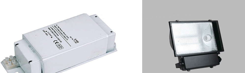
Magnetic ballast is relatively large size and weight, their power consumption, noise. The electronic ballast with low voltage starter, no flicker, no noise, energy efficient, bright lights instantly advantages, electronic ballasts have a broader space for development.
This circuit rectifier filter circuit, a power switch and the drive circuit, the ballast circuit with the filament load of three parts. Composed of various elements of the circuit functions as follows:
① rectifier diode VD1 ~ VD4 and filter capacitor C1, C2 in series form a bridge rectifier and filter circuit, the function is to be filtered by the rectifier 220V AC in C1, C2 ends get unloaded 310V DC voltage, high frequency inverters for the back circuit to provide operating power.
② power transistor VT1, VT2, used as a switch, working in saturation and cut-off state, the switch faster.
③ resistors R1, R6 is a start-up resistor is provided VT2 conduction initial bias, and thus stimulate VT1, VT2 form a self-excited oscillation.
Meanwhile resistor R1 and capacitor C3 connected in parallel buck-start circuit, to some extent reduce the damage caused by overvoltage. To ensure reliable operation of the capacitor C3, the pressure value should be chosen more than twice the supply voltage, C3 voltage is 630V.
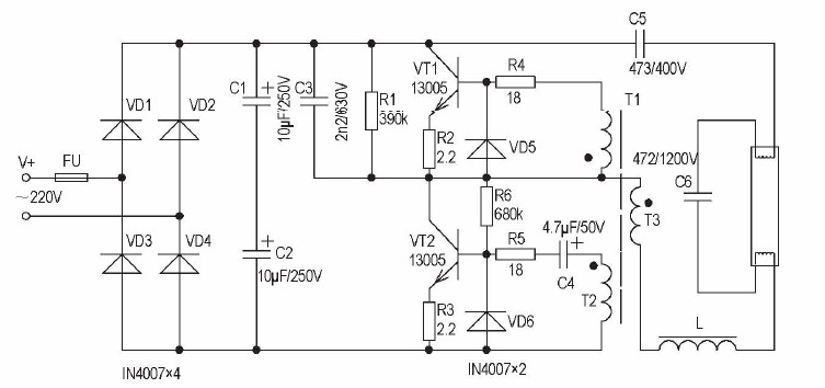
④ diodes D5 and D6, and its role is to protect the transistor VT1, VT2, in parallel with the transistor base-emitter charge storage effect can be greatly reduced, thereby improving the transistor switching speed.
⑤ starting signal transformer T mutual coupling. It is composed of a single-strand wire T1, T2, T3 formed around the ring, with the switch driving circuit portion are closely interdependent relationship between the parameters so that they in the production process more difficult to determine. This circuit T1 is three laps, T2 is 3 laps, T3 is 5 laps.
⑥ VT2 capacitor C4 and connected in between the base and the emitter, base and emitter to prevent a potential mutation, to a certain extent protect the transistor VT2.
⑦ resistors R2, R3, R4, R5 for the protection resistor, to protect the transistor, but the effect is limited.
⑧ capacitor C5 is the start capacitor, blocking flow of a role of the exchange to prevent a DC voltage of 310V directly into the fluorescent tube, to allow a high frequency AC voltage through 20kHz.
⑨ choke L, the resonant capacitor C6 form a series resonant circuit, its role is limited starter fluorescent tube and lamp operating current.
Electronic ballast 20W and 40W basic function is to power frequency of 50Hz 20kHz frequency power to convert, and direct light fluorescent tubes. Their work is: After power on, the rectified DC voltage 310V filtered through C3, R1 and R5 in parallel and then in series, to provide a base of VT2 narrow current pulse so VT2 first conduction. In VT2 conduction period, the current flow path is: + V → C5 → upper filament lamp lower filament lamp → C6 → L → → choke transformer T3 → VT2 collector - emitter → to form a loop, for resonant charging capacitor C6. Coil of the transformer T T1 and T2, T3 on inductive coupling effect, T1 will induced voltage on the transistor VT1 conduction, and the induced voltage on T2 will VT2 end. In VT1 saturated conduction period, the current flow path is: resonant capacitor C6 → lamp filament → C5 → VT1 top of the collector - emitter → transformer T3 → lower filament lamp choke L → → C6, the current flow is The discharge circuit for the C6. With the coupling of the transformer T, the transistor VT1, VT2 alternating conduction, the output square wave pulse voltage, this voltage through the choke coil L, the filament resistance, C6 series resonant component in generating a high voltage pulse across C6, the fluorescent ionized mercury vapor tubes form a conductive path and the breakdown lamp lit. Start-up circuit, the capacitor C4 through diode D6 and transistor VT2 quickly discharged to prevent VT2 saturated conduction state can not exit. When the fluorescent tube is lit, its resistance sharp decline in parallel with the resistance across C6, C6 ends it down to a normal operating voltage (about 80V), to maintain a stable normal fluorescent tube light.
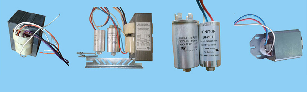
Metal Halide Ballasts | High Pressure Sodium Ballasts | Fluorescent ballasts | Gear Tray
Links: Porcelain lamp socket | Mercury Vapor Ballast | Light bulb socket
Xml Copyright: @2012-2020 James Lighting Electronic Co.,Ltd


 EMAIL US
 SKYPE
SKYPE