
Electronic ballasts overhaul Step 1. Fluorescent lamps up to failure is not lit, turn on the lights without any reaction. First, measure R0 is blown. RO itself from the insurance role, once the overcurrent will be blown, in order to avoid damage to more components. RO Department received some ballast is 0. 5A fuse. If the RO blown, there must be an overcurrent fault. Replace R05 inch at a place off (see photo), measured with a multimeter Rx10k block resistance across the mains lead should 2Mf above (R1 + R2 series value); swap table pen test, it should be the same. If the two, with a diode rectifier bridge blown; if more than 2Md2, then C1, C2 leakage; if this resistance value in accordance with that request, which can be electrically measuring a, b two points should be a DC voltage of about 300V. But sometimes a power-on blown RO, this is a short-circuit bridge rectifier diode, should be by the side of the amount of D1-D4 positive and negative resistance. Rectifier diode is very small probability of damage, and the filter capacitor damaged more, especially such as drawings, C1 and C2 in series, it will cause a chain reaction, a capacitor breakdown, the other also will be damaged. Replacement, the best selection of voltage 300V capacitor. (2) In determining the rectifier filter circuit well, and then proceed to check later in the circuit. As a place disconnected block is measured with a multimeter RX10k a, b resistance between two points (red pen then b, black pen then a), this value should be greater than 500kSZ. If you are 00, you should check the R10, VT2's ce between poles is blown; 470kn If so, then in between poles of VT2 ce serious leakage, short circuit or even presented here is easy to misjudge a problem when barium "a, b Only 30kf between resistance around like VT2 leakage, it is not true, because the block with 1 OkS2 measurement table 9V voltage is applied to a, b, the bias current injection to VT2, VT2 conduction state, so ce between resistance, not leak. 3 Determine a, b between the resistance is correct, measured with a multimeter Rxlk files and VT2 VTl two PN junction resistance, largely determine the performance of these two transistors. It should be noted that the PN junction resistance measured VT1, to disconnect R5, to get the correct reading. Rxl block with R5 to 1110 measured resistance values for these resistors are blown examples. Blown 119,1110 more common, this two resistors are used for too long resistance will increase, as long as their value is greater than 2dZ, the circuit is not easy to start-up, the lamp is not lit, should focus on checking. As D5, D6, C4 of the pressure is high, the winding diameter thick magnetic transformer Trl, insulation or, which are not damaged. 4 After the above static measurements, checked the faulty components, the circuit is reset, carefully check the circuit board solder joints and components for short-circuit, touch, loose, broken places. After adjusting correct power, in most cases, fluorescent able to resume normal work, but may also occur following failure, should each be ruled out.
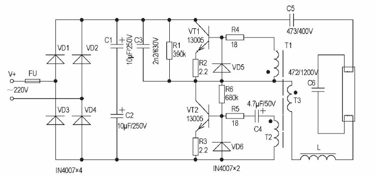
(1) still appears overcurrent, continue burning RO, this is mainly VT1 or VT2 ce between the pressure of an F drop, there is high pressure soft breakdown, you must use enough pressure triode replacement. In addition, C3 or C5 lack of pressure, use a multimeter to check it out, preferably using a 500V welding shake table test its insulation resistance should be o0, or as leakage. (2) the tube ends redness, brightness is clearly insufficient. At this time, the first block with a multimeter measuring AC voltage across the lamp, should be about 100V. This is only reference, not the actual number because the voltage across the lamp is not a standard sine waveform, and the frequency above 20kHz, over the frequency range multimeter. If this voltage is less than 100V are more likely VT1 or VT2 performance degradation, low level of conduction. No case of an oscilloscope, digital multimeter test two of the be voltage around a 0.4V, if the deviation is too large, or even positive, indicating that the tube is not in saturated conduction state, the test tube should be changed, do not blindly adjust circuits. If the lamp has reached the end pressure 100V, still glow is not normal, it is the poor performance of the lamp. Fluorescent tubes typically judged good or bad, just measured filament resistance, if the filament is not broken, the tube is no large-scale black, depending on its integrity. However, despite its inferior lamp filament is not broken, the tube no black marks, but it is not working. (3) Lamp brightness is insufficient, a spiral tube aperture, which is flowing through the lamp current is small, mainly because of the capacity of C5 drop too much, it may be in both ends and then a 2.2nF1630V C5 capacitor test again. Various brands of fluorescent ballasts, the resonant capacitor C5 is not the same capacity, roughly between the 3-10nF its capacity is too large or too small will cause the lamp does not shine
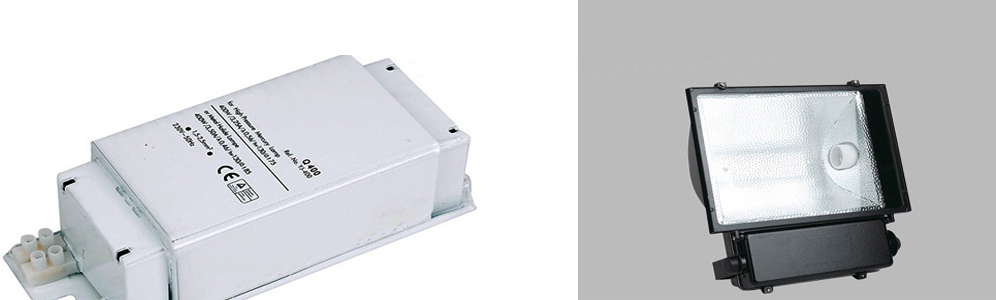
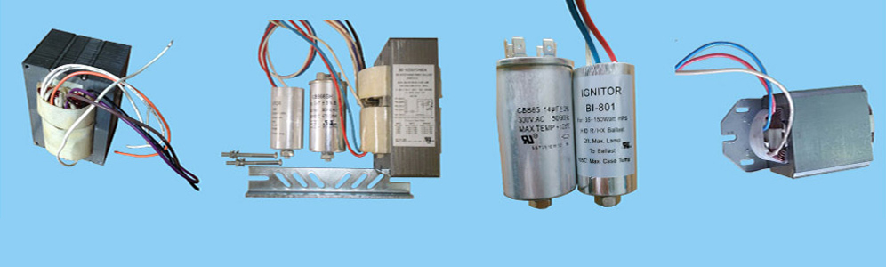
Metal Halide Ballasts | High Pressure Sodium Ballasts | Fluorescent ballasts | Gear Tray
Links: Porcelain lamp socket | Mercury Vapor Ballast | Light bulb socket
Xml Copyright: @2012-2020 James Lighting Electronic Co.,Ltd


 EMAIL US
 SKYPE
SKYPE